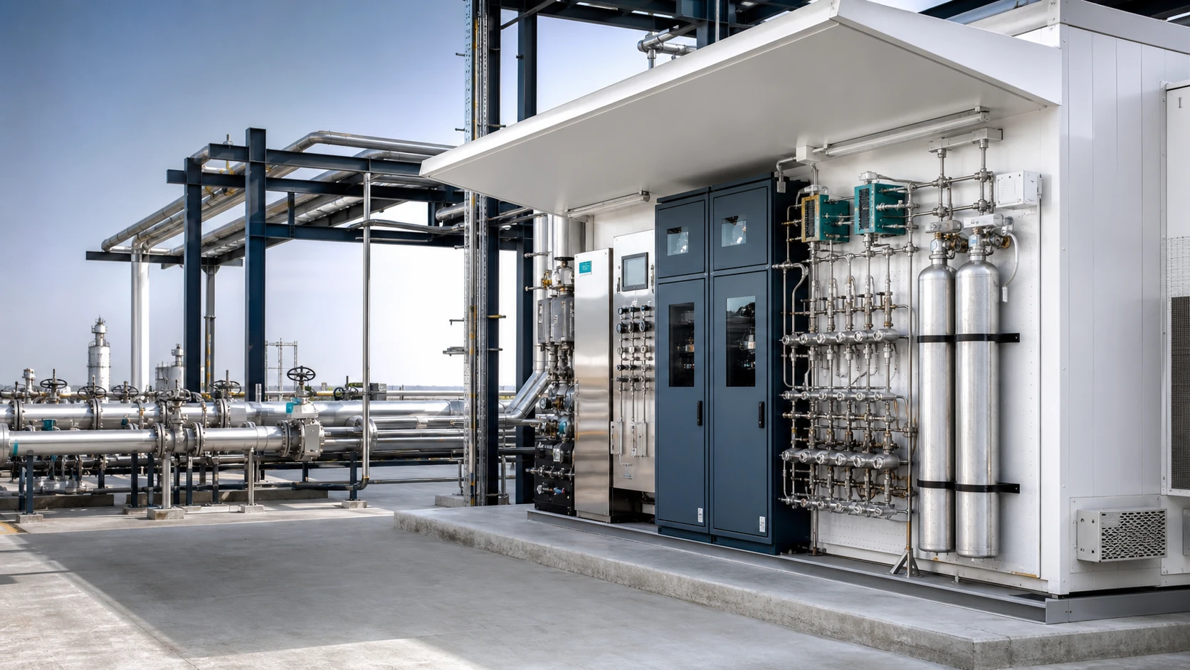
This technical page defines the engineering basis, supply boundaries and enquiry data for Analyzer Shelter Systems. Each project is configured around capacity, feed composition, product specification, ambient conditions, available utilities and the owner’s operating requirements rather than a fixed catalogue arrangement.
Engineering of Analyzer Shelter Systems concentrates on sample representativeness, transport lag, phase integrity, pressure and temperature conditioning, filtration, calibration, analyzer response, shelter environment and hazardous-area requirements. The selected configuration is verified against normal, minimum, start-up, shutdown and credible upset cases, then checked for operability, maintainability, energy use, process safety and site interfaces before the design is frozen.
Rated capacity, minimum stable load, feed envelope, inlet and outlet conditions, product specification, start-up and shutdown cases, design life and acceptance criteria are agreed before equipment definition is frozen. Measurement basis also fixes turndown, custody-transfer accuracy, sample conditioning, response time, calibration philosophy, shelter conditions and hazardous-area requirements.
Mechanical design and materials
Materials, corrosion allowance, sour-service requirements, piping classes, nozzle design, insulation, coating, supports and maintenance access are coordinated with the actual process conditions and project code hierarchy.
Control, safeguarding and operation
Control philosophy, alarms and trips, cause-and-effect logic, interlocks, start-up and shutdown sequences, safe depressurization and operator access are developed consistently from the P&IDs through functional testing.
Layout, utilities and interfaces
Battery limits, tie-in points, structural loads, cabling, instrumentation, drains, vents, access routes, lifting envelopes and shipping constraints are controlled through coordinated models and interface drawings.
From project definition to delivery
Clear inputs and contract-ready outputs
Proposal quality depends on complete input data and an explicit acceptance basis. The following lists provide a practical starting point and are completed during technical clarification.
Recommended RFQ information
Feed flow, composition and credible operating envelope
Inlet conditions, required product specification and pressure-drop limit
Site and ambient data, hazardous-area classification and HSE requirements
Available utilities with pressure, temperature and capacity
Applicable standards, materials, supply limits and owner document formats
Typical engineering and supply deliverables
Design basis, heat and material balance, and process description
PFDs, P&IDs, equipment list and technical datasheets
Control philosophy, cause and effect, I/O definition and utility summary
Plot plan, 3D model, foundation loads and fabrication drawings
Inspection and test plans, FAT records, final data book and commissioning support
Delham Engineering
Define the scope around real project data
Send the available process data, battery limits and expected document list for a technical proposal. The engineering team will identify missing information through a structured clarification register.